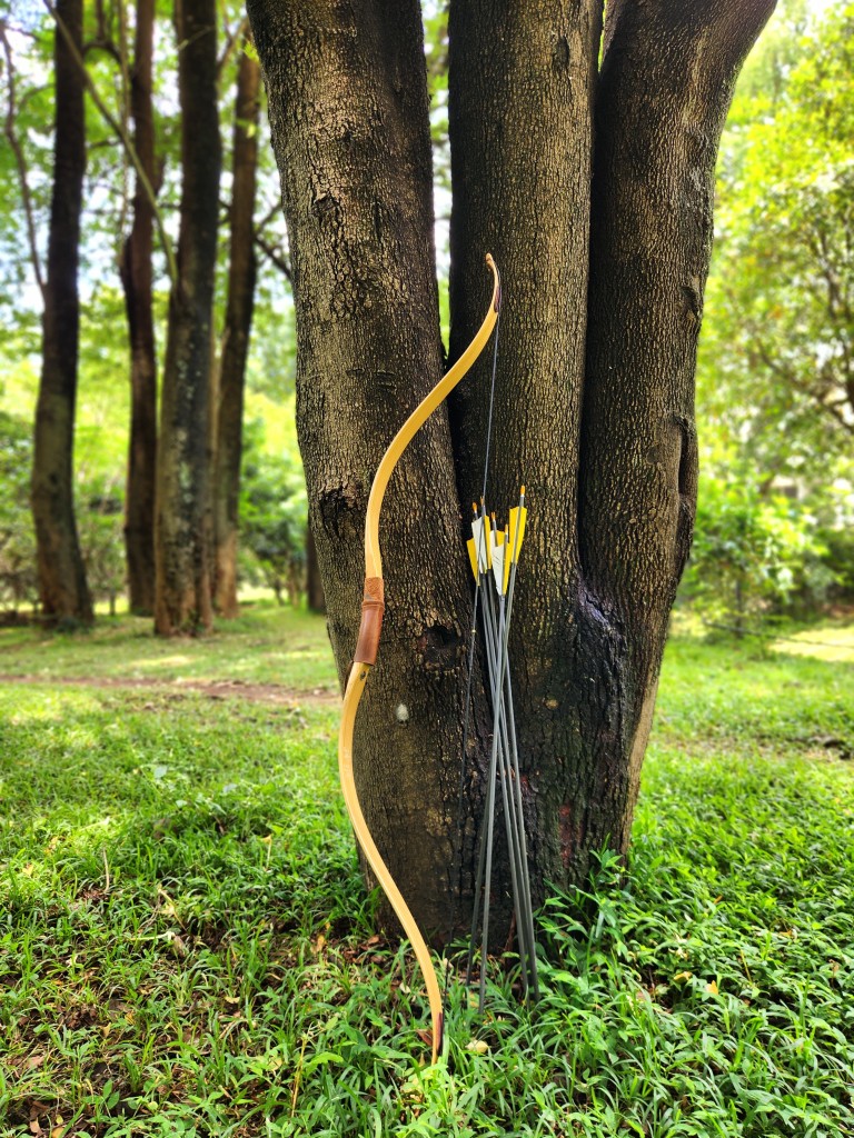
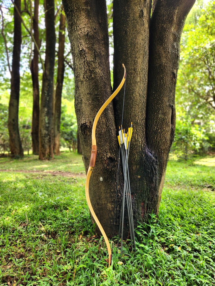
I enjoy making conceptual connections across different disciplines. When I learned about “impedance matching” in electronics, I realized that this concept is not limited to the world of electronics. Impedance matching is an interesting and tricky topic in RF circuits. Since I practice archery, I’ll share an archery analogy of impedance matching that can help develop an intuitive understanding.
In archery, arrows are tuned to match the bow. Many factors determine a good match, but we will only focus on the weight of the arrow for our example. Suppose you shoot an arrow that weighs 26 grams (~400 grains) from a bow with a 40 lb draw weight. In archery terminology, we would say that the arrow is 10 GPP (grains per pound), since 400 / 40 = 10. The energy stored in the limbs of the bow would get transferred to this arrow. If you use a lighter arrow (< 10 GPP), the arrows will certainly fly faster. However, if it is too light, it won’t be able to effectively penetrate the target. You will also feel significant hand shock when shooting arrows that are too light for your bow. Shooting very light arrows could potentially damage the bow as it would be akin to dry firing. Now, think of the opposite case, where we shoot very heavy arrows (>10 GPP). Imagine shooting a thick branch! The arrow would be too slow to do any real damage to the target.

The ideal arrow weight is somewhere in between the two extremes. When the arrow is close to the ideal weight, it would carry the most energy. So, what are we doing when we are finding this ideal weight? In electronics, this is called impedance matching.
In the context of RF transmitters, we are trying to maximize the energy going into the antenna. This can only happen if the impedances are matched. If there is a mismatch, there will be power loss and energy will be reflected. In extreme cases, the reflected energy could damage the transmitting circuit (similar to dry firing a bow).
This is easy to understand with a simple resistive circuit:

In the above circuit, power transfer would be optimal when Zₛ equals Zₗ. This can be verified with simple math. If we make Zₗ < Zₛ, the current (I) would certainly increase. However, the voltage across the load would drop. Similarly, if we made Zₗ > Zₛ, the voltage across the load would increase, but at the cost of current. So, optimal power (V*I) would be transferred when Zₛ = Zₗ.
Matching source and load impedance is not always desirable in electronics. For example, if we were designing a “stiff” voltage source that provides a steady voltage, we would want the source impedance (Zₛ) to be significantly lower than the load impedance (Zₗ). Otherwise, the load overload the voltage source and pull the voltage down. However, when driving a speaker from an amplifier, or when sending radio waves with an antenna, we want optimal power transfer. In these cases, impedance matching is desirable.
