I live in an apartment where installing an antenna for HF use is a challenge. After evaluating various antenna options, I chose to install the so-called ‘random wire’ antenna, stretching it between my balcony and my aunt’s next door. Random wire antennas aren’t very random at all! Certain lengths perform better than others. I decided to go with a 58-ft wire based on the recommendations on this website.
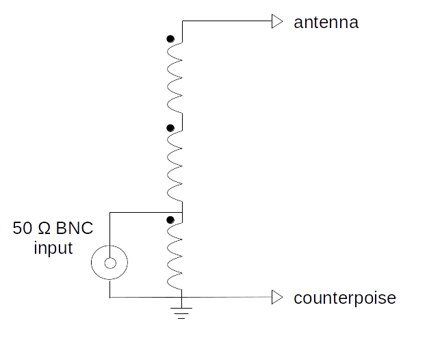
A random wire antenna has an unpredictable impedance that varies with frequency. Moreover, the impedance is usually so high that most antenna tuners need additional help from a 9:1 unun transformer to bring the impedance down to a workable range. The 9:1 unun is an autotransformer with a 3:1 turns ratio, which results in a 9:1 impedance transformation.
I had an untested unun that I built a long time ago. I connected it to the antenna and used 25-ft of coax to connect it to my Emtech ZM-2 antenna tuner. Despite all my efforts to tune it on the 40m band, I failed to bring the SWR to an acceptable range.
I tried adjusting the antenna length, but it didn’t make much of a difference. The SWR was too high when I checked with the NanoVNA. What was wrong in my setup? It was time to sit on my armchair, put on my detective hat, and light a cigar.

My hunch was that the untested 9:1 unun was the culprit. To confirm this, I removed the antenna wire from the unun and replaced it with a 470-ohm resistor on the output. If the transformer was doing what it was supposed to, I expected an impedance of approximately 50 ohms (470/9) on the output.
I used the NanoVNA to plot the transformer’s frequency response. The frequency plot revealed the problem. The 9:1 transformation was happening around 30 Mhz. At 7 MHz (40m band), it was nowhere close to 9:1. No wonder the tuner was struggling!

In the plot, the yellow trace is the impedance. In an ideal world, a transformer would exhibit consistent performance across all frequencies. However, in reality, a transformer’s bandwidth is influenced by its inductance and various parasitic elements. The VNA trace shows that the impedance increases between 1-30 MHz, where it is approximately 50 ohms. The 9:1 transformation occurs near 30 MHz, signaling that the low cut-off frequency is higher than optimal—a clear indicator of insufficient inductance! Time to light another cigar.
I wasn’t sure what toroid core I was using in the unun. I decided to replace it with an FT50-43 toroid that I had in my junk box. Mix #43 toroids can be used for wideband transformers between 3-60 MHz according to this website. The FT50-43 is a small toroid, so it was a bit difficult to fit 3 wires side by side. I used a twisted trifilar winding to save space and get about 8-9 turns on the core. The inductance increased from about 3 uH (old core) to 230 uH (new core). On the NanoVNA, the impedance response looked much more uniform across the HF band.

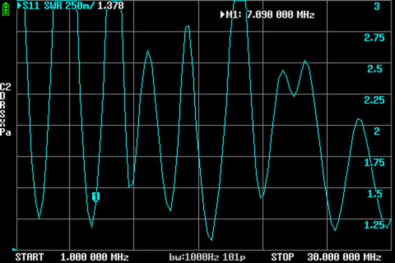
I connected the random wire antenna to the unun and measured the SWR across the HF band with the VNA. The impedance varies with frequency, with dips at specific frequencies. As you can see, there is a dip in the 40m band that allows the ZM-2 to easily tune the antenna.

I connected some of my QRP transmitters to the antenna, and was able to hear them on Bangalore’s webSDR!
There are still some unresolved mysteries to explore. Do I need a separate counterpoise? Would that make a difference? I haven’t observed any noticeable improvements from adding one. I believe the coax shield is the counterpoise in my setup. Does the position or orientation of the 25-ft coax cable make any difference? It does seem to affect the antenna’s impedance, so I think it does. How does the angle of my antenna affect propagation? So much to explore, so little time!
