Archery and Electronics

I enjoy making conceptual connections across different disciplines. When I learned about “impedance matching” in electronics, I realized that this concept is not limited to the world of electronics. Impedance matching is an interesting and tricky topic in RF circuits. Since I practice archery, I’ll share an archery analogy of impedance matching that can help develop an intuitive understanding.

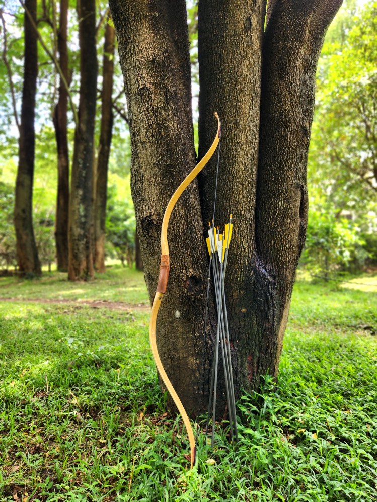
In archery, arrows are tuned to match the bow. Many factors determine a good match, but we will only focus on the weight of the arrow for our example. Suppose you shoot an arrow that weighs 26 grams (~400 grains) from a bow with a 40 lb draw weight. In archery terminology, we would say that the arrow is 10 GPP (grains per pound), since 400 / 40 = 10. The energy stored in the limbs of the bow would get transferred to this arrow. If you use a lighter arrow (< 10 GPP), the arrows will certainly fly faster. However, if it is too light, it won’t be able to effectively penetrate the target. You will also feel significant hand shock when shooting arrows that are too light for your bow. Shooting very light arrows could potentially damage the bow as it would be akin to dry firing. Now, think of the opposite case, where we shoot very heavy arrows (>10 GPP). Imagine shooting a thick branch! The arrow would be too slow to do any real damage to the target.

The beautiful Gera Fox Max bow with matching arrows

The ideal arrow weight is somewhere in between the two extremes. When the arrow is close to the ideal weight, it would carry the most energy. So, what are we doing when we are finding this ideal weight? In electronics, this is called impedance matching.

In the context of RF transmitters, we are trying to maximize the energy going into the antenna. This can only happen if the impedances are matched. If there is a mismatch, there will be power loss and energy will be reflected. In extreme cases, the reflected energy could damage the transmitting circuit (similar to dry firing a bow).

This is easy to understand with a simple resistive circuit:

In the above circuit, power transfer would be optimal when Zₛ equals Zₗ. This can be verified with simple math. If we make Zₗ < Zₛ, the current (I) would certainly increase. However, the voltage across the load would drop. Similarly, if we made Zₗ > Zₛ, the voltage across the load would increase, but at the cost of current. So, optimal power (V*I) would be transferred when Zₛ = Zₗ. 

Matching source and load impedance is not always desirable in electronics. For example, if we were designing a “stiff” voltage source that provides a steady voltage, we would want the source impedance (Zₛ) to be significantly lower than the load impedance (Zₗ). Otherwise, the load overload the voltage source and pull the voltage down. However, when driving a speaker from an amplifier, or when sending radio waves with an antenna, we want optimal power transfer. In these cases, impedance matching is desirable.

Waves in the Ether

I’ve always been fascinated by electronics and radio waves. It’s something we take for granted these days. But think about it – you can push electrons back and forth in a wire, and the effects of this swashing could be sensed thousands of miles away. Isn’t that magical? I didn’t study electronics in college – my major was CS. We learned how to write code and design algorithms. I learned electronics through self-education and experimentation. I feel that this style of learning is often better than a formal education. You can take things at your own pace and be driven by your curiosity and passion. My interest in electronics began with me trying to control things in my house with my computer (see my old blog). One of my first projects was connecting an LED to my computer’s parallel port. Later on I figured out how to connect all kinds of things, such as a floppy drive camera pannerRC cars, etc.

I watched a documentary that left a strong impression – “Shock and Awe: The Story of Electricity” (by Jim Al-Khalili). This film inspired me to learn more about electronics and go beyond controlling LEDs and relays. Soon, I became obsessed with radio circuits. My first transmitter/receiver was a primitive spark-gap transmitter and coherer receiver that I built. My interest in radios eventually pushed me to get an amateur radio license (callsign N6ASD) in 2015.

Spark-gap transmitter
Coherer receiver

The person who has inspired me the most in my electronics journey is Frank Harris (K0IYE). He is the author of the book “From Crystal Sets to SSB”. I couldn’t put this book down once I began reading it. His approach and passion for learning were something I could relate to. It wasn’t long before I contacted the author. After exchanging emails for about a year, I met him in person when I visited Colorado in 2017. For me, it was like a dream come true to meet my electronics hero in real life! He showed me his basement lab, with all his radios and electronics creations. Over the years, we’ve stayed in touch and Frank continues to inspire me. If you read Frank’s book, you will find my name mentioned in a few places (particularly in the sections about regenerative receivers and homebrew electrolytic capacitors).

Meeting Frank Harris (K0IYE)

In 2020, I moved from San Francisco to Bangalore. Many things changed in my life, and electronics took a backseat. I focussed my time on other non-technical hobbies. Fast forward to 2023, I found myself back in the world of electronics. My wife (Aditi) encouraged me to set up a little workstation in a corner of my apartment. Having a space in your house/apartment dedicated to something you enjoy is important, and makes it easier to pursue your hobby.

Oil lamps and electronics – a great combination!

These days, I am building a 40-meter QRP (low power) transmitter from Frank’s book (chapter 6). The circuit consists of multiple stages – the oscillator, buffer amplifier, driver, and final power amplifier. So far, I have completed the first two stages – the oscillator and buffer amplifier. I don’t have the transistors that Frank is using in his circuit in the final stages. So, I plan to design my own driver/power amplifier stages. I’m planning to use transistors that are readily available in India.

The joy of successful oscillations

Stay tuned for updates!