The SolderSmoke Direct-Conversion Receiver

I have been on the on the lookout for a receiver to pair with my Nandi-40 transmitter. When I came across the SolderSmoke Direct-Conversion Receiver challenge, it seemed perfect. It checked all the right boxes: 40m band, fully analog,  built entirely with discrete components, no ICs in sight. This project was originally intended for high-school students to build and learn about electronics and radio. This simple receiver has gained a following in the ham radio homebrewing community.

While browsing the project’s Discord channel, I “liked” one of the posts and Bill Meara (N2CQR) noticed it. If you’re not already familiar with Bill, he runs the popular SolderSmoke podcast and website. He emailed me and said I should also build the receiver! How could I say no?

Bill and I have known each other for a while. I first discovered his work through his book, Global Adventures in Wireless Electronics. If you appreciate the magic of radio and electronics, I would strongly recommend reading his book. The book is a memoir of Bill’s radio adventures, and it captures the thrill of the hobby. Bill has written about some of my projects on the SolderSmoke website.

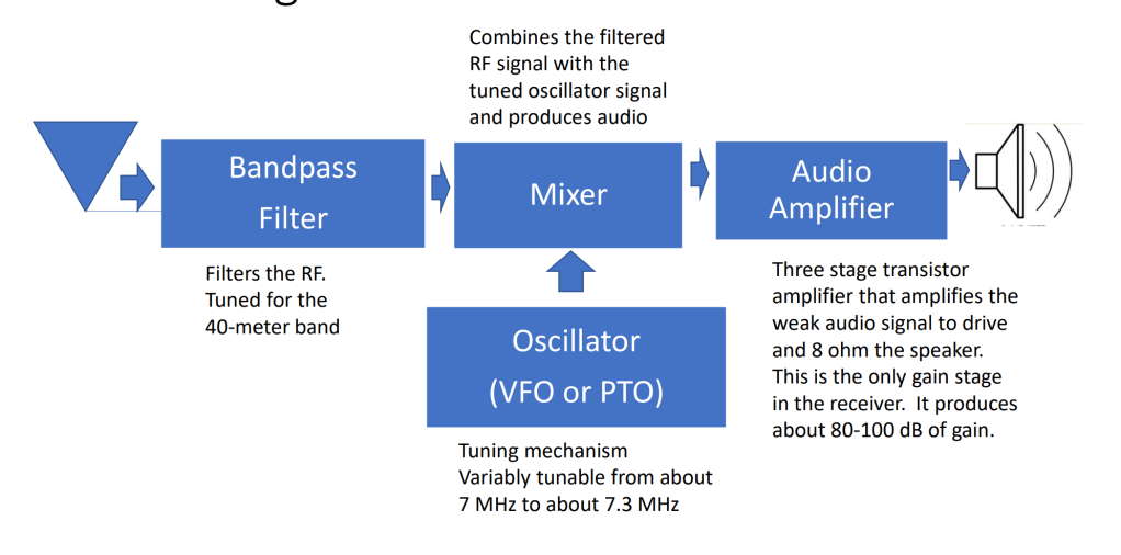
The receiver consists of four sections: a band-pass filter, an oscillator, a mixer, and an audio amp. Usually, folks build each module on a separate board. I like this approach to building because it is perfect for experimentation, even though it may not be the most compact. You can test and modify individual sections easily.

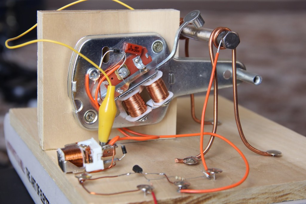
I started off by building the mixer, the heart of this receiver. It is a double-balanced diode ring mixer. Alan Wolke (W2AEW) has some excellent videos on this topic. To test the mixer, I fed signals from a signal generator into the RF and LO (Local Oscillator) ports and terminated the output with a 50-ohm load.

To verify that mixing was happening, I tuned a nearby shortwave radio to the difference frequency of the two input signals. When both signals were applied, the radio went quiet—proof that the mixer was generating a signal at the expected intermediate frequency.  I also used the math function on my oscilloscope to view the mixing products and calculate the conversion loss. It was fun to see theory meet practice.

Mixer
Mixer with audio diplexer close-up

Next, I added the audio diplexer circuit which extracts the audio signal and terminates the unwanted higher-frequency components. Before moving on to the other modules, I wanted to verify that the mixer could actually receive a signal. I hooked up a signal generator to act as the VFO and borrowed an audio amplifier from another project for testing. And sure enough, it worked! I could hear signals coming through, which was a great moment of validation.

However, it quickly became clear that a band-pass filter was essential. Without it, the receiver was swamped with strong AM broadcast stations bleeding in from all over the band. Front-end filtering was necessary for selectivity.

I built the band-pass filter next. I didn’t have NP0 capacitors, so I used regular ceramic capacitors that I had in my junk box along with some trimmer capacitors. With a NanoVNA, I measured the insertion loss. It was on the high side at around -2.8 dB. Not ideal. However, I decided to continue on and revisit the band-pass filter later when I had better capacitors.

Tuning the band-pass filter

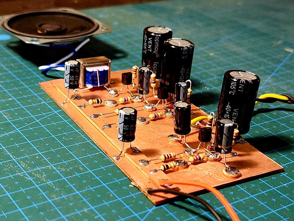
The audio amp is a straightforward 3-stage amplifier. The only part I didn’t have was the output transformer, which I was able to order online. The amp had a tendency to oscillate, but it works better with a stiffer 9V supply using two batteries in parallel.

Audio amp

Next, I built the VFO, which is a simple Colpitts oscillator with a JFET buffer stage. What’s interesting is that the oscillator uses an inductor for tuning. It is based on the design by Ashhar Farhan (VU2ESE) from his Daylight Again radio. The tuning coil is wound on a 3D-printed former. The original designed called for stable mica capacitors in the oscillator, but I couldn’t find them anywhere in Bangalore. I spent an entire afternoon navigating the crowded lanes of SP Road in search of these elusive capacitor with no luck. So, I built it with regular ceramic capacitors and hoped for the best. Needless to say, the oscillator drifted all over the place.

Eventually, I ordered surface-mount NP0 capacitors online. They were easily available, much cheaper than mica capacitors, but a pain to solder. After a few fumbled attempts, I somehow managed to solder them in place. The oscillator is now rock stable and hardly drifts at all.

I also swapped out the fixed capacitors in the band-pass filter with surface-mount NP0 capacitors and the insertion loss dropped down to about -0.4 dB. These capacitors were definitely worth the soldering hassle.

In the end, I hooked all the modules together and the receiver worked perfectly.

The final receiver

My first modification was an essential one: adding a power switch and a status LED. After that, I added a connector for an external speaker. It sounds amazing with an enclosed speaker. The connector auto-disconnects the internal speaker when an external one is plugged in, eliminating the need for a separate speaker selector switch.

External speaker connector

Here is Bill’s writeup on my project. It is officially in the SolderSmoke Hall of Fame.

Here are some videos of the receiver in action:

SSB:

CW:

WSPR-ing Around the World

I feel that one of the charms of amateur radio is its unpredictability. It feels like throwing a message in a bottle into the vast ocean, not knowing where the currents would take it, or who would read the message. Radio waves often take unpredictable paths when traveling. To a large extent, how these waves propagate is determined by the state of our planet’s ionosphere. The ionosphere consists of layers of charged particles that affect how RF signals travel. These layers move and shift and undergo cycles of strengthening and weakening, all under the influence of the Sun. Radio waves can bounce off the ionosphere, and essentially “skip” around the Earth.

To understand how waves propagate in different bands a protocol known as WSPR (pronounced “whisper”) was developed in 2008 by Joe Taylor (K1JT). It is an acronym for “Weak Signal Propagation Reporter”. It can tell us what is possible with low-power transmissions and see which radio bands have a path to which points on the globe.

A WSPR transmission conveys the sender’s call sign, station location, and power level using a compressed data format with strong forward error correction (FEC). The message is modulated using frequency-shift keying (FSK) at a very low bit rate. Sending a single WSPR message takes almost two full minutes! The WSPR protocol is effective at signal-to-noise ratios (SNR) as low as -28 dB in a 2500 Hz bandwidth, some 10 to 15 dB below the threshold of audibility.

My QCX transceiver contains an inbuilt WSPR mode. I set it up and sent a single WSPR message on the 40m band with about 4-5 watts of power. It took almost 2 minutes to send, and I was worried about heating the BS170 transistors in the power amplifier since I had never really stress-tested them in this manner. To my relief, no magic smoke was released. I monitored the transmission on a local WebSDR to make sure it was sending a decipherable message. After it was done sending, I checked the WSPRNet website to see if any stations received my feeble signal. I wasn’t expecting anything spectacular, but to my surprise, the signal had traveled much farther than I imagined!

My WSPR signal travels the world

I had reached Antarctica, Hawaii, New Zealand, Australia, the Canary Islands, and Norway (to name a few)! Well, that proves that the antenna I built is working. There are lots of tools to analyze the WSPR data. I liked the analysis tools available on WSPR Rocks. For example, you can view a SNR vs distance chart. It was interesting to see that some distant stations copied my signal better than stations which were nearby. On the website you can see the names of the stations and other details.

I also pulled all the data into a Google Sheet for analysis.

I reached 26 locations with a single WSPR transmission. Incredible! The results have encouraged me to try building a dedicated WSPR beacon using the Raspberry Pi for use on other bands. Stay tuned!

The Not-so-Random “Random Wire” Antenna

I live in an apartment where installing an antenna for HF use is a challenge. After evaluating various antenna options, I chose to install the so-called ‘random wire’ antenna, stretching it between my balcony and my aunt’s next door. Random wire antennas aren’t very random at all! Certain lengths perform better than others. I decided to go with a 58-ft wire based on the recommendations on this website.

A random wire antenna has an unpredictable impedance that varies with frequency. Moreover, the impedance is usually so high that most antenna tuners need additional help from a 9:1 unun transformer to bring the impedance down to a workable range. The 9:1 unun is an autotransformer with a 3:1 turns ratio, which results in a 9:1 impedance transformation.

9:1 unun schematic

I had an untested unun that I built a long time ago. I connected it to the antenna and used 25-ft of coax to connect it to my Emtech ZM-2 antenna tuner. Despite all my efforts to tune it on the 40m band, I failed to bring the SWR to an acceptable range.

9:1 unun

I tried adjusting the antenna length, but it didn’t make much of a difference. The SWR was too high when I checked with the NanoVNA. What was wrong in my setup? It was time to sit on my armchair, put on my detective hat, and light a cigar.

Time for some detective work

My hunch was that the untested 9:1 unun was the culprit. To confirm this, I removed the antenna wire from the unun and replaced it with a 470-ohm resistor on the output. If the transformer was doing what it was supposed to, I expected an impedance of approximately 50 ohms (470/9) on the output.

I used the NanoVNA to plot the transformer’s frequency response. The frequency plot revealed the problem. The 9:1 transformation was happening around 30 Mhz. At 7 MHz (40m band), it was nowhere close to 9:1. No wonder the tuner was struggling!

The 9:1 unun’s terrible frequency response

In the plot, the yellow trace is the impedance. In an ideal world, a transformer would exhibit consistent performance across all frequencies. However, in reality, a transformer’s bandwidth is influenced by its inductance and various parasitic elements. The VNA trace shows that the impedance increases between 1-30 MHz, where it is approximately 50 ohms. The 9:1 transformation occurs near 30 MHz, signaling that the low cut-off frequency is higher than optimal—a clear indicator of insufficient inductance! Time to light another cigar.

I wasn’t sure what toroid core I was using in the unun. I decided to replace it with an FT50-43 toroid that I had in my junk box. Mix #43 toroids can be used for wideband transformers between 3-60 MHz according to this website. The FT50-43 is a small toroid, so it was a bit difficult to fit 3 wires side by side. I used a twisted trifilar winding to save space and get about 8-9 turns on the core. The inductance increased from about 3 uH (old core) to 230 uH (new core). On the NanoVNA, the impedance response looked much more uniform across the HF band.

Uniform frequency response with the FT50-43 toroid

I connected the random wire antenna to the unun and measured the SWR across the HF band with the VNA. The impedance varies with frequency, with dips at specific frequencies. As you can see, there is a dip in the 40m band that allows the ZM-2 to easily tune the antenna.

Random wire impedance after a 9:1 unun

I connected some of my QRP transmitters to the antenna, and was able to hear them on Bangalore’s webSDR!

There are still some unresolved mysteries to explore. Do I need a separate counterpoise? Would that make a difference? I haven’t observed any noticeable improvements from adding one. I believe the coax shield is the counterpoise in my setup. Does the position or orientation of the 25-ft coax cable make any difference? It does seem to affect the antenna’s impedance, so I think it does. How does the angle of my antenna affect propagation? So much to explore, so little time!

Waves in the Ether

I’ve always been fascinated by electronics and radio waves. It’s something we take for granted these days. But think about it – you can push electrons back and forth in a wire, and the effects of this swashing could be sensed thousands of miles away. Isn’t that magical? I didn’t study electronics in college – my major was CS. We learned how to write code and design algorithms. I learned electronics through self-education and experimentation. I feel that this style of learning is often better than a formal education. You can take things at your own pace and be driven by your curiosity and passion. My interest in electronics began with me trying to control things in my house with my computer (see my old blog). One of my first projects was connecting an LED to my computer’s parallel port. Later on I figured out how to connect all kinds of things, such as a floppy drive camera pannerRC cars, etc.

I watched a documentary that left a strong impression – “Shock and Awe: The Story of Electricity” (by Jim Al-Khalili). This film inspired me to learn more about electronics and go beyond controlling LEDs and relays. Soon, I became obsessed with radio circuits. My first transmitter/receiver was a primitive spark-gap transmitter and coherer receiver that I built. My interest in radios eventually pushed me to get an amateur radio license (callsign N6ASD) in 2015.

Spark-gap transmitter
Coherer receiver

The person who has inspired me the most in my electronics journey is Frank Harris (K0IYE). He is the author of the book “From Crystal Sets to SSB”. I couldn’t put this book down once I began reading it. His approach and passion for learning were something I could relate to. It wasn’t long before I contacted the author. After exchanging emails for about a year, I met him in person when I visited Colorado in 2017. For me, it was like a dream come true to meet my electronics hero in real life! He showed me his basement lab, with all his radios and electronics creations. Over the years, we’ve stayed in touch and Frank continues to inspire me. If you read Frank’s book, you will find my name mentioned in a few places (particularly in the sections about regenerative receivers and homebrew electrolytic capacitors).

Meeting Frank Harris (K0IYE)

In 2020, I moved from San Francisco to Bangalore. Many things changed in my life, and electronics took a backseat. I focussed my time on other non-technical hobbies. Fast forward to 2023, I found myself back in the world of electronics. My wife (Aditi) encouraged me to set up a little workstation in a corner of my apartment. Having a space in your house/apartment dedicated to something you enjoy is important, and makes it easier to pursue your hobby.

Oil lamps and electronics – a great combination!

These days, I am building a 40-meter QRP (low power) transmitter from Frank’s book (chapter 6). The circuit consists of multiple stages – the oscillator, buffer amplifier, driver, and final power amplifier. So far, I have completed the first two stages – the oscillator and buffer amplifier. I don’t have the transistors that Frank is using in his circuit in the final stages. So, I plan to design my own driver/power amplifier stages. I’m planning to use transistors that are readily available in India.

The joy of successful oscillations

Stay tuned for updates!